

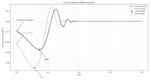
Over the past year, there has been a rapid deployment of renewable energy around the world, driven by international CO₂ emission reduction targets. However, the faster these new facilities are implemented, the more challenging it becomes for the system to adapt. Nevertheless, this represents an opportunity to innovate and improve its ability to adapt to this new type of generation. As a result, challenges such as inertia, power ramps, voltage instability and frequency instability arise. Figure 1 illustrates an example of how key indicators of a power system’s health can be affected by the loss of inertia. It shows that the frequency nadir is lower and the Rate Of Change of Frequency (RoCoF) is higher in a power system with less inertia.
The literature presents numerous studies aimed at addressing these challenges arising from the increased use of inverter-based generators (IBRs). Among the proposed solutions, droop response and inertia emulation have been identified as the most effective algorithms for mitigating stability issues. However, the large volume of control strategies proposed for converters can be overwhelming for the industry. To ensure effective coordination, it is essential to find a balance between the most innovative proposals and the practical needs of the sector.
Figure 1. Comparison of frequency deviation in the event of inertia loss.
Grid-Following (GFL) Converters as Part of the Solution
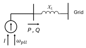
Most inverter-based generators are based on grid-following (GFL) converter topology, which means they require an external grid to operate. As the name suggests, GFL converters follow the external voltage waveform and frequency. A key component of this topology is the Phase-Locked Loop (PLL), which ensures continuous synchronisation of the converter with the grid by frequently sampling the spatial voltage vector (usually using Clarke and Park transformations). A typical simplified model of this type of topology is a current source behind a series impedance. A diagram of this model is illustrated in Figure 2.
This feature allows GFL-based IBRs to have a very fast response, offering significant advantages over traditional generation. A notable benefit is their fast response at the converter interconnection point (less than one cycle). For this reason, GFL converters can ‘emulate’ instantaneous phenomena, such as inertial response, to help reduce the rate of change of frequency (ROCOF), mimicking the oscillation equation of traditional synchronous machines and providing a fast primary frequency response (droop response) [1].
However, the use of GFL technology for frequency support has certain limitations, including:
- Voltage imbalances: When connected to the distribution network, voltage imbalances can arise, requiring advanced PLL designs (e.g., Double Decoupled Synchronous Reference Frame PLL), which can affect inertial response.
- High sensitivity to ROCOF: If ROCOF is too high, the PLL may lose its angular reference, disabling frequency response capability.
- Low short-circuit contribution: This limits the converter’s ability to support the grid under fault conditions.
Figure 2. Simplified model of inverters based on GFL topology.
Grid-Forming Converters (GFM) as a Solution
The nature of inertia is based on energy storage elements. In mechanical systems, inertia is stored as kinetic energy, with velocity as the state variable representing its level. Similarly, electrical systems store energy in inductors or capacitors in the form of magnetic or electric fields.
In renewable energy systems, inverters typically employ a back-to-back configuration with a capacitor in the DC link between the primary source and the IGBT bridge. This DC capacitor stores energy, with voltage as its state variable. Without a frequency support algorithm, converters can naturally deliver their inherent inertia to the grid through their DC link capacitors.
This opens up opportunities to improve inertia by integrating supercapacitors, avoiding the need for inertia emulated from GFM-based Battery Energy Storage Systems (BESS). Although promising, this strategy is still in the research stage and could take years to be adopted by the industry.
Regulations and Trends
Due to the large number of proposals for GFM converter control loops, the industry is seeking to standardise interconnection requirements for inverter-based generation technologies. In addition, organisations such as WECC are proposing standardised models for use not only in industry but also in academic studies.
- WECC models: The Western Electricity Coordinating Council has published two models to standardise GFM control loops:
- REGFM_A1: Emulates internal speed using a droop strategy [4].
- REGFM_B1: Creates a Virtual Synchronous Machine, simulating inertial response with a virtual rotor [5].
- ENTSO-E requirements: The European Network of Transmission System Operators for Electricity has defined requirements for GFM technologies, including inertia ranges, black start capability, dynamic behaviour (voltage source response behind an impedance), internal impedance ranges (physical and virtual), primary response, ride-through capability, among others. Spain is expected to adapt and approve this document by 2025 [6].
Centralised vs. Decentralised Inertia: Challenges and Future Prospects
Ongoing research explores centralised and decentralised inertia approaches (provided by a power plant controller or locally at each inverter). This raises key questions for the future:
- Is a decentralised inertial response sufficient?
This solution mimics the behaviour of conventional synchronous machines. This response is a spontaneous local response at the converter level and has no specific target at the POI. Unlike synchronous machine-based power plants, converter-based power plants require a significantly larger number of generation units to achieve the same rated power at the POI, and an internal network to evacuate energy from the generation units to this point. This difference means that decentralised inertial response alone is an option, but not sufficient to coordinate an effective inertial response at the POI.
- Can a plant provide a centralised inertial response?
This option is challenging given the current response delays at the POI of renewable plants. However, centralised inertia emulation using a Power Plant Controller (PPC) would enable a coordinated response to the frequency measured at the POI. In this topology, the PPC sends power references to each inverter in the plant, eliminating the need for major changes to the inverter control to provide local inertia response. Future advances in communication technologies would allow for faster plant response and enable PPCs to provide more accurate and rapid centralised inertia responses at the POI.
- What about a combined, centralised and decentralised inertial response?
The local inertial response could act in shorter time windows, taking advantage of the faster response of this configuration, while the centralised response can coordinate each inverter in a longer time window to ensure the desired response at the POI. This approach could provide a fast and coordinated inertial response at the POI level, meeting future grid code requirements. Research into the combined response of centralised and decentralised control is key in this context.
BIBLIOGRAPHY
[1] Remus Teodorescu; Marco Liserre; Pedro Rodriguez, “Grid Converter Control for WTS,” in Grid Converters for Photovoltaic and Wind Power Systems , IEEE, 2007, pp.205-236, doi: 10.1002/9780470667057.ch9.
[2] W. Du, Z. Chen, K. P. Schneider, R. H. Lasseter, S. Pushpak, F. K. Tuffner, and S. Kundu, “A comparative study of two widely used grid forming droop controls on microgrid small signal stability,” pp. 1–1.
[3] W. Du et al., “A Comparative Study of Two Widely Used Grid-Forming Droop Controls on Microgrid Small-Signal Stability,” in IEEE Journal of Emerging and Selected Topics in Power Electronics, vol. 8, no. 2, pp. 963-975, June 2020, doi: 10.1109/JESTPE.2019.2942491.
keywords: {Voltage control;Inverters;Microgrids;Power system stability;Stability analysis;Low pass filters;Frequency control;Droop control;grid-forming;inverter;microgrid;stability},
[4] R. W. Kenyon, A. Sajadi, A. Hoke and B. -M. Hodge, “Open-Source PSCAD Grid-Following and Grid-Forming Inverters and A Benchmark for Zero-Inertia Power System Simulations,” 2021 IEEE Kansas Power and Energy Conference (KPEC), Manhattan, KS, USA, 2021, pp. 1-6, doi: 10.1109/KPEC51835.2021.9446243. keywords: {Computational modeling;System integration;Power system stability;Inverters;Stability analysis;Mathematical model;PSCAD;inverter-based resources;generic models;PSCAD;zero inertia;power system stability},
[5] Western Electricity Coordinating Council, “Model Specification of Droop-Controlled, Grid- Forming Inverters (REGFM_A1)”, USA, 2023.
[6] Du, Wei, Sebastian Achilles, Deepak Ramasubramanian, et al., 2024. Virtual Synchronous Machine Grid-Forming Inverter Model Specification (REGFM_B1). UNIFI-2024-6-1
[7] European Network of Transmission System Operators for electricity “Grid Forming capability of power park modules”